Please note: Although this item is marked as in stock, our Elsema stock is consistently replenished to meet demand. Due to frequent bulk orders, stock levels can be challenging to determine in real-time. If you need an estimated time of arrival (ETA), please feel free to contact us, and we’ll be happy to assist!
Features:
Eight-Channel Receiver with Relay Output: Provides flexible control options, perfect for applications requiring reliable signal transmission.
Over 4 Billion Code Combinations: Offers an exceptionally high level of security, virtually eliminating the risk of code grabbing or interference.
Unlimited Transmitter Capacity: Can store an unlimited number of transmitters, making it ideal for large-scale operations.
User-Selectable Output Modes: Supports momentary, latching, and security latching output modes, allowing customisation to suit different operational needs.
Versatile Power Supply: Compatible with both 12 – 24 Volts AC or DC, offering flexibility in installation and application.
Highly Sensitive Receiver Input Stage: Ensures reliable performance with an operating range of up to 350 meters when paired with GLT433 transmitters.
High Load Switching Capacity: Capable of switching loads up to 8 Amps, making it suitable for heavy-duty industrial applications.
Crystal Controlled Stability: The crystal-controlled design guarantees high stability and performance, ensuring consistent operation under varying conditions.
Advanced Microcontroller Technology: This receiver uses re-programmable microcontroller technology, allowing it to be adapted to unique applications and providing future-proofing for evolving needs.
Power ON LED Indicator: Easy monitoring of the receiver’s power status for quick diagnostics.
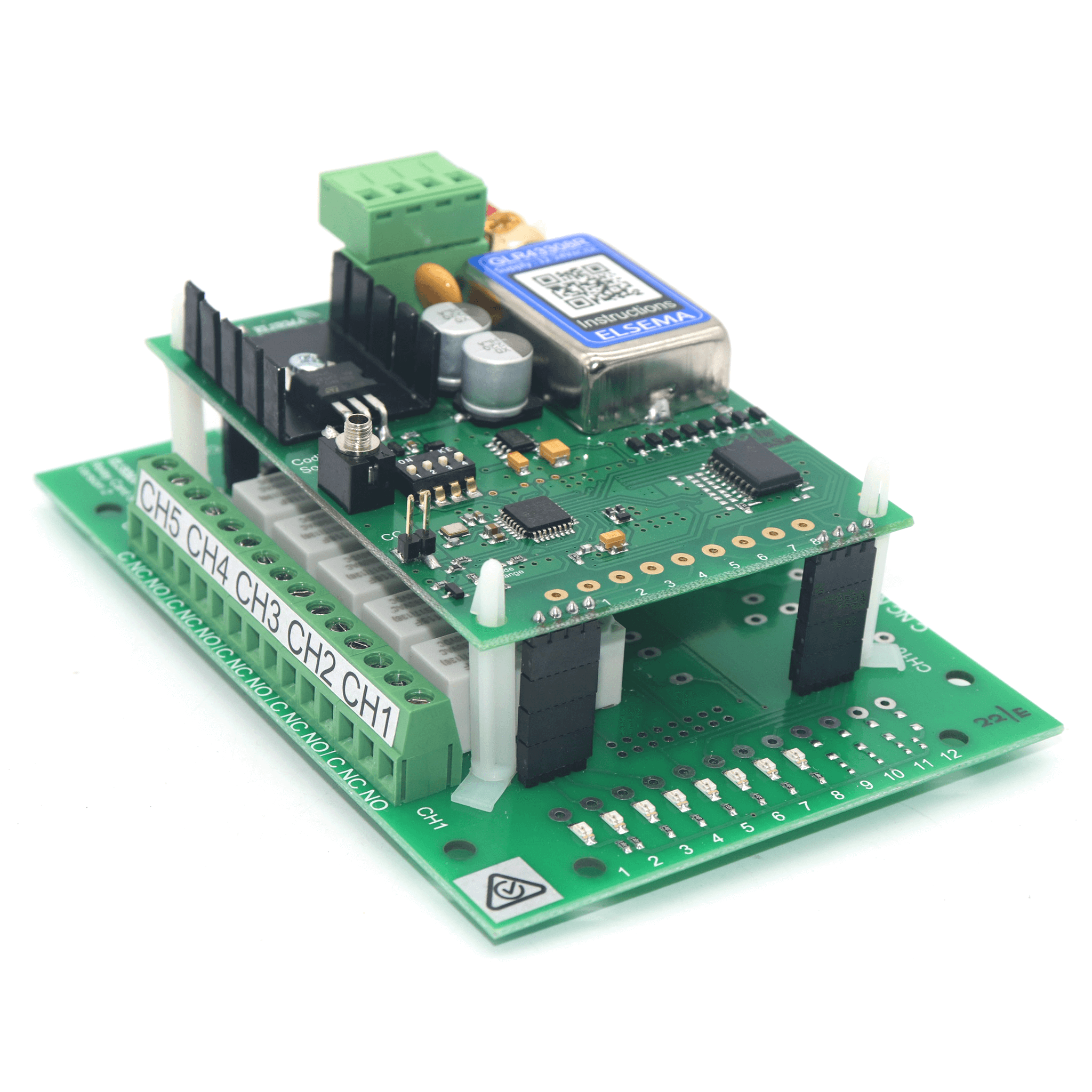
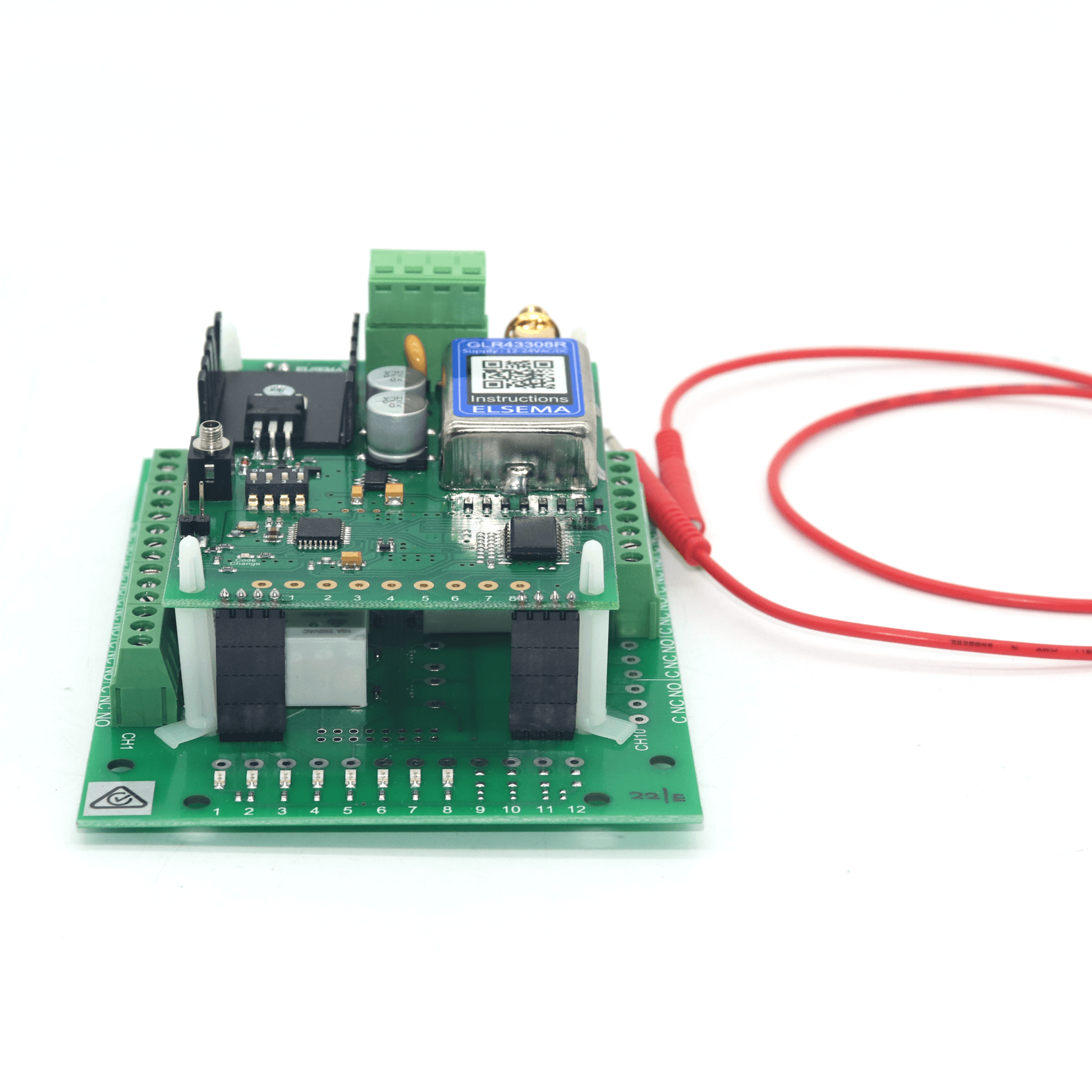
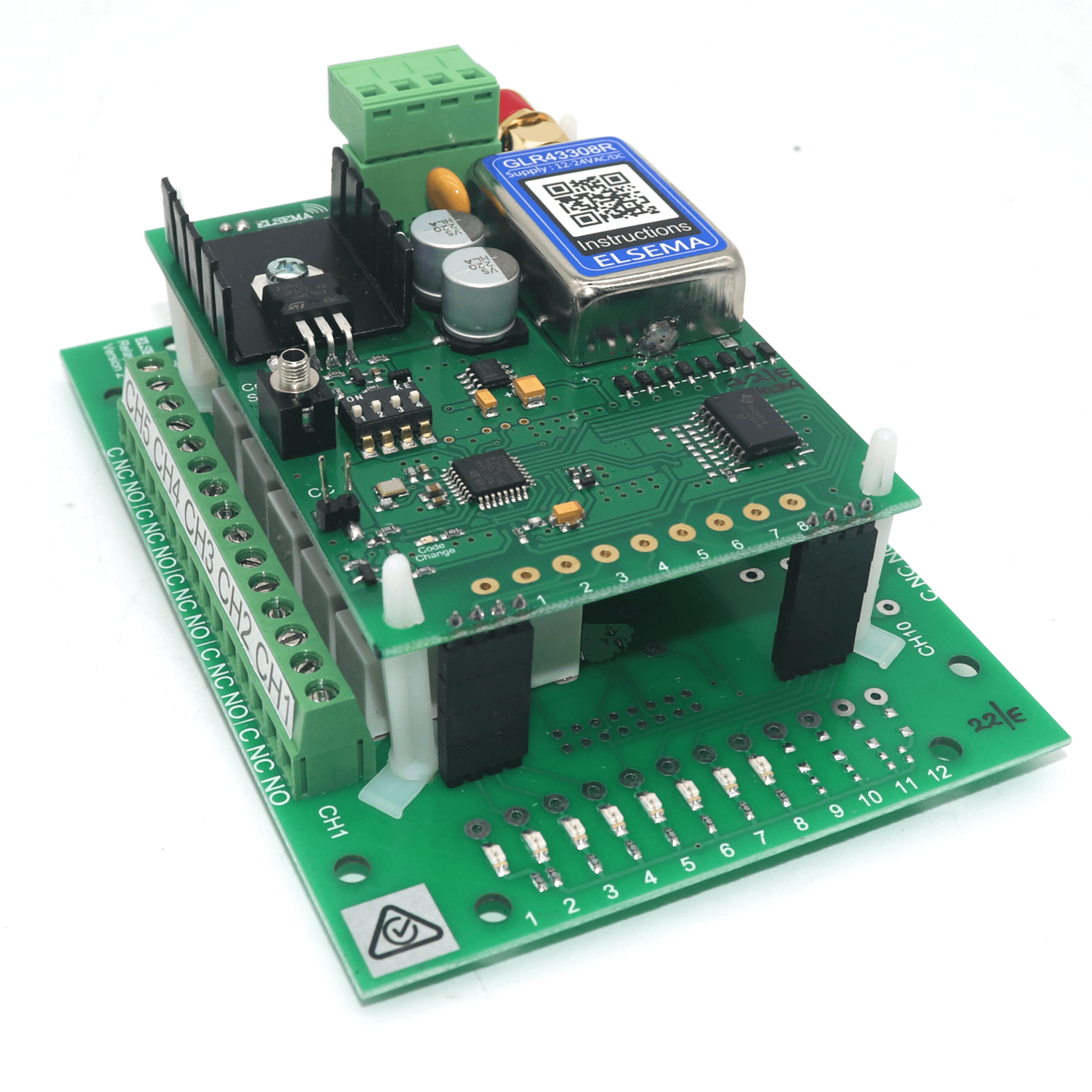
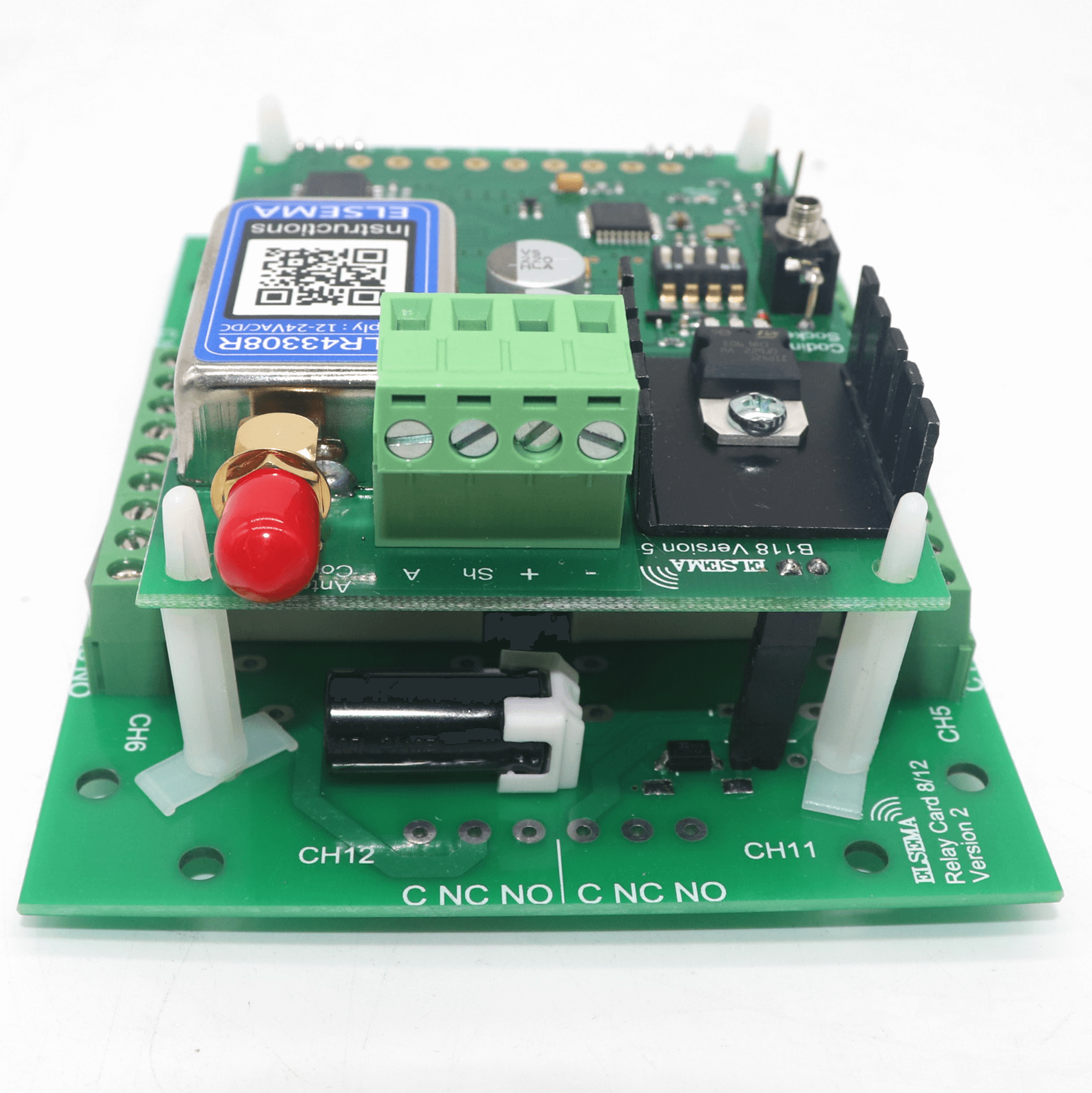
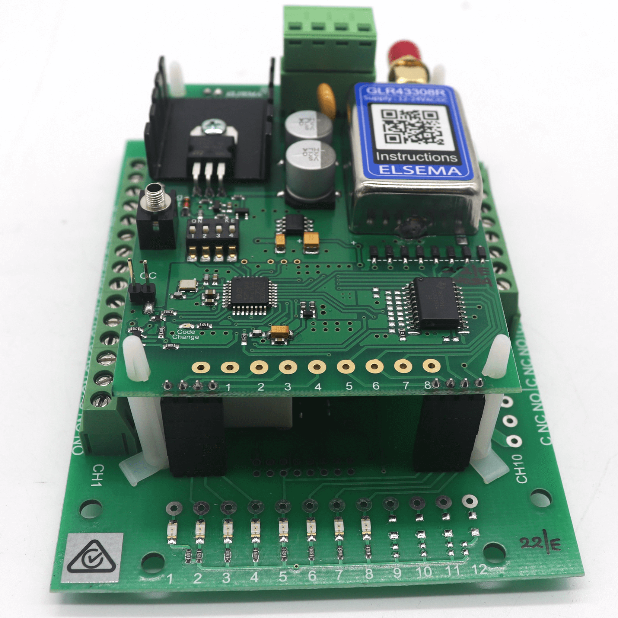
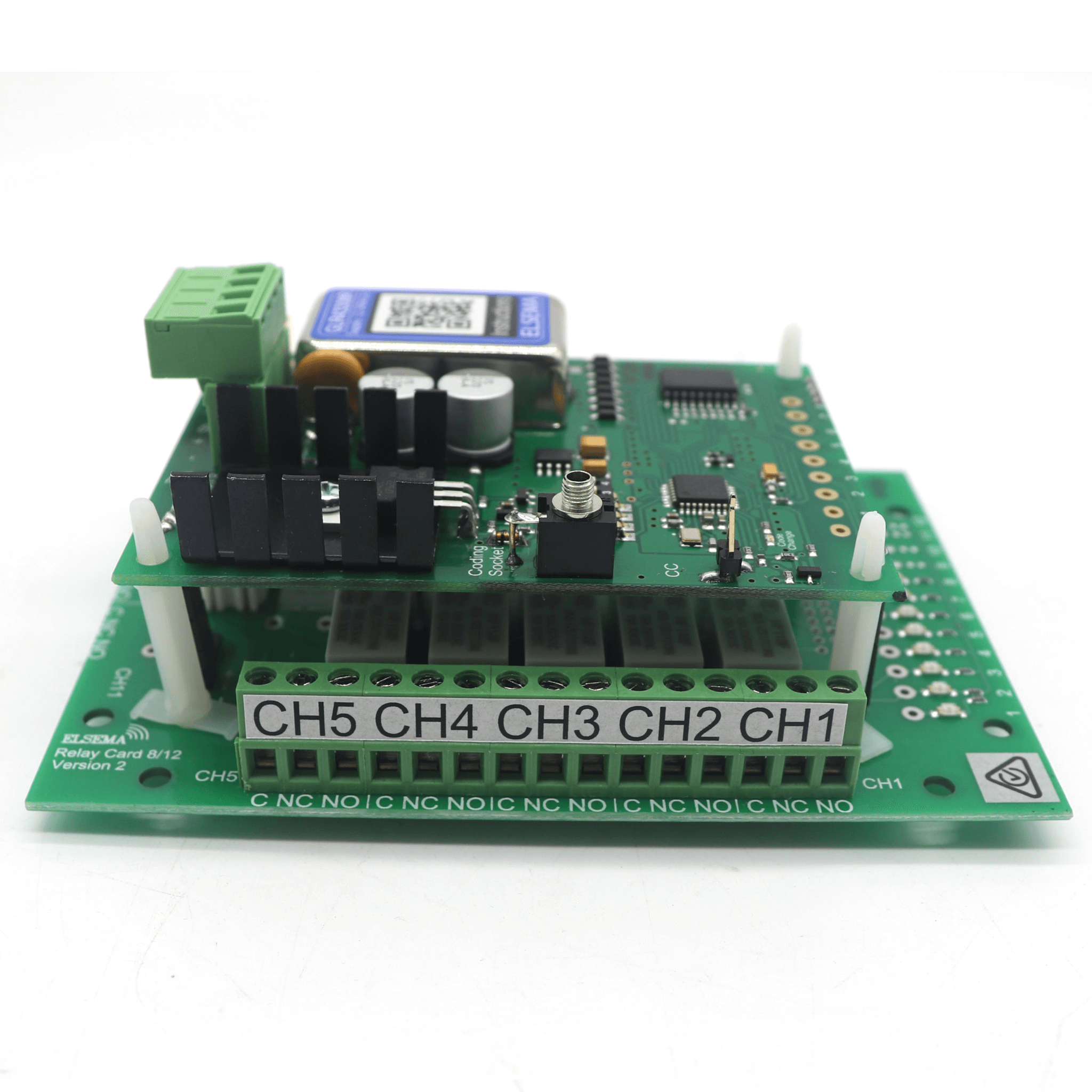
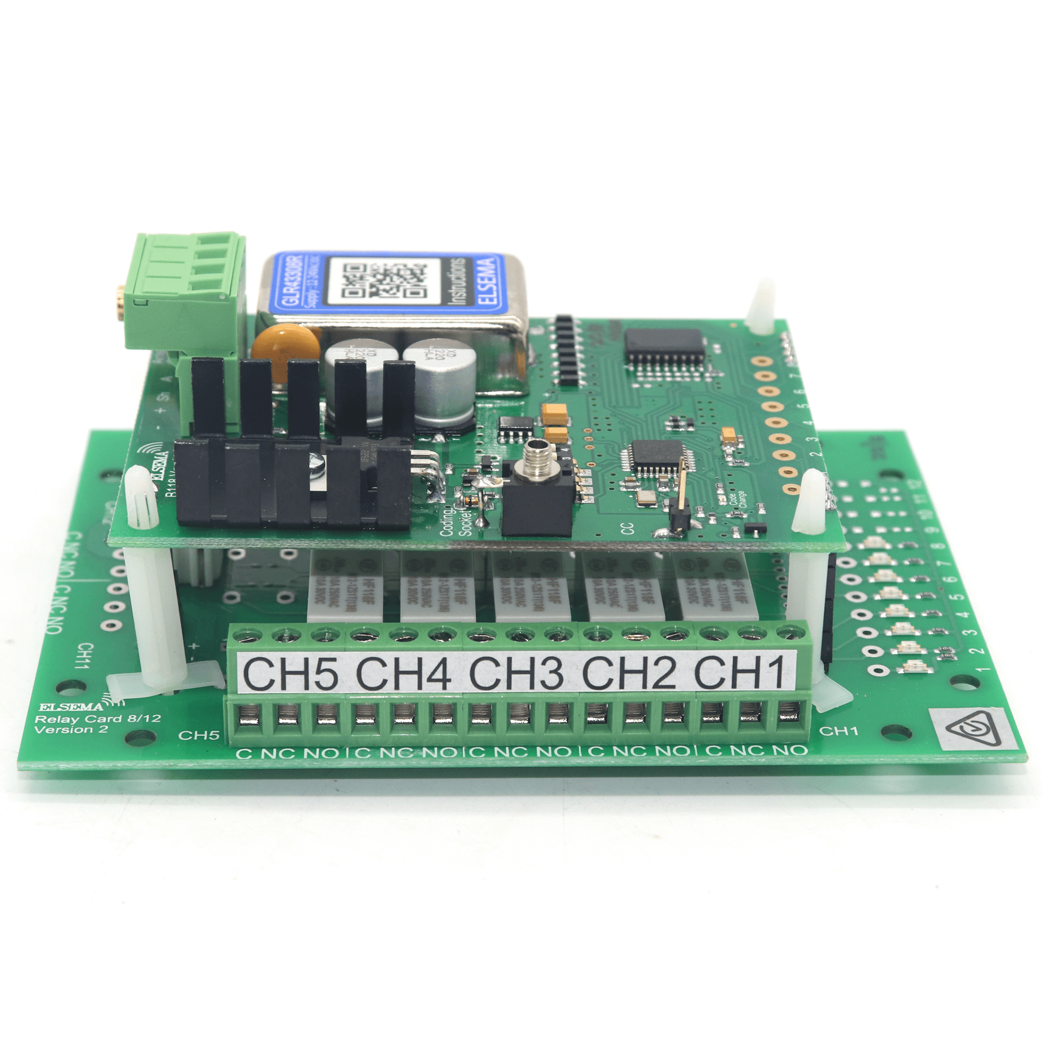
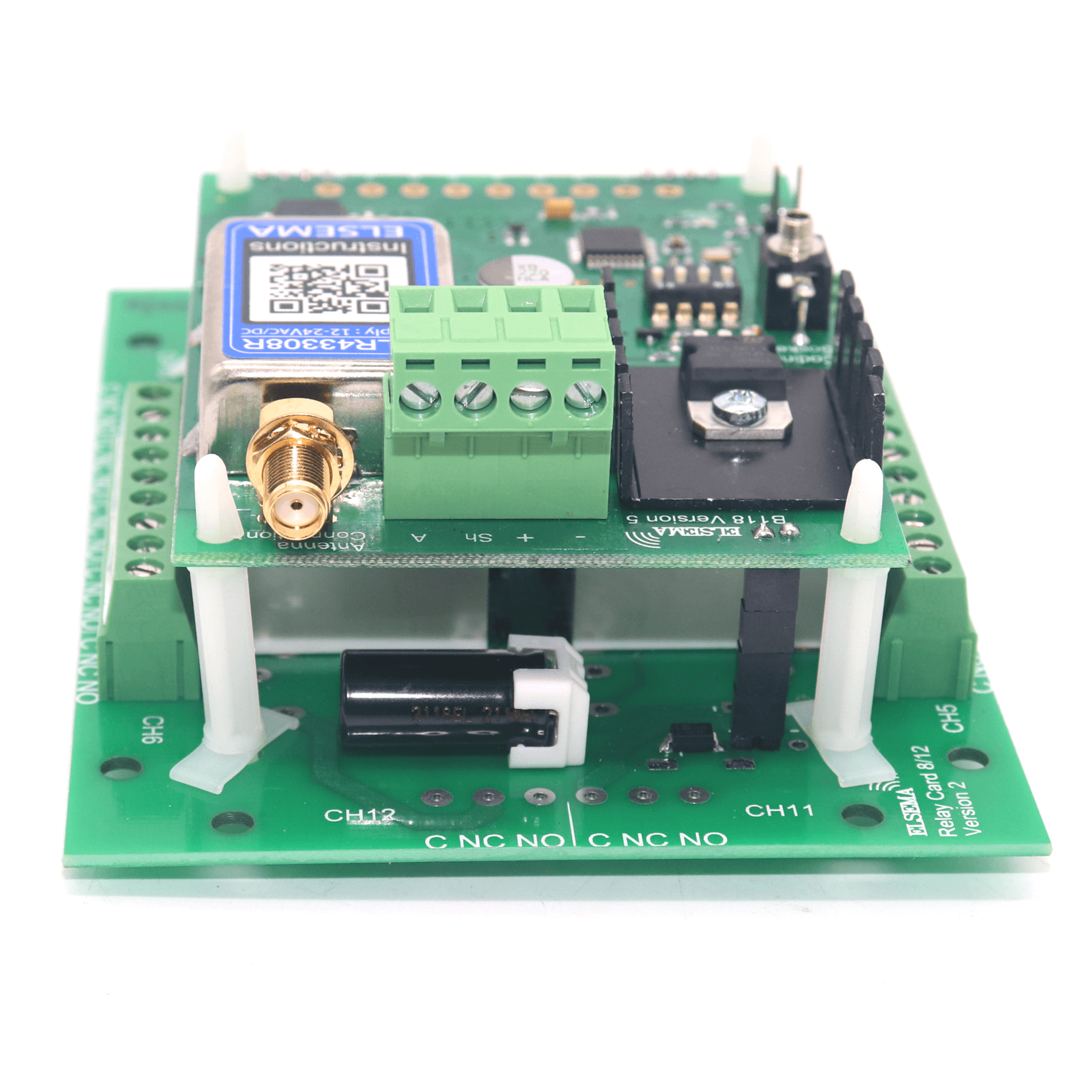
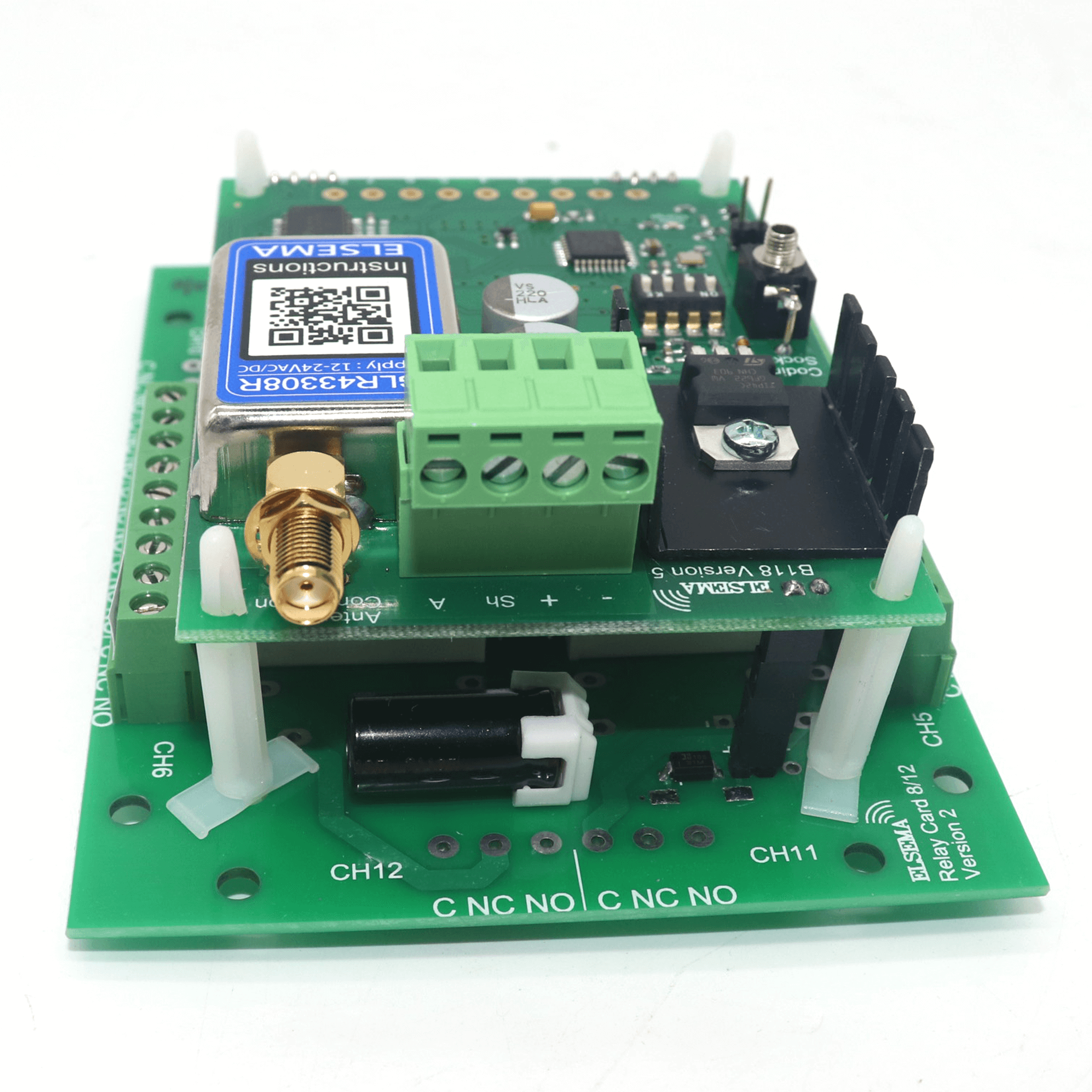
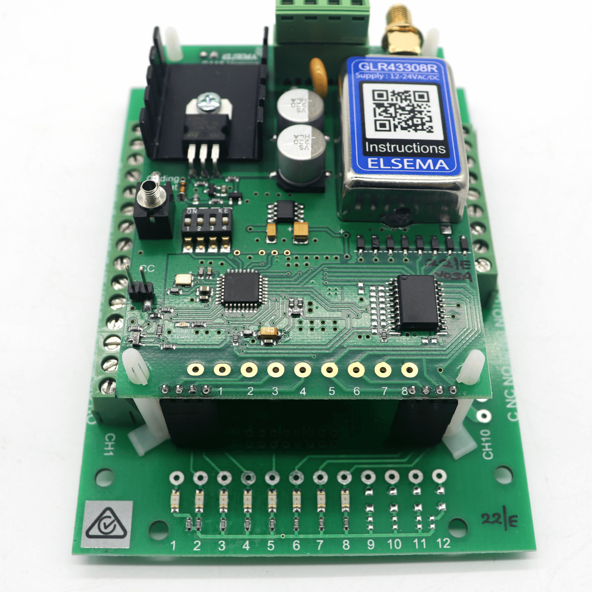
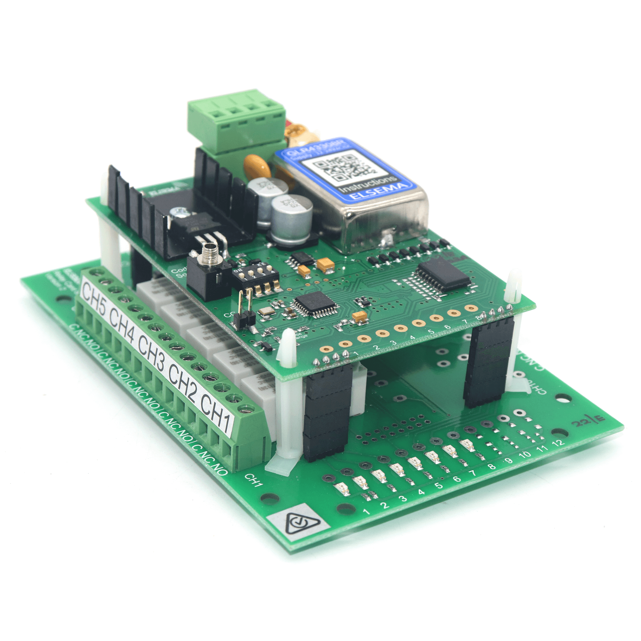
The Elsema GLR43308R Receiver is an advanced 8-channel Gigalink® receiver designed for both industrial and residential automation. It allows seamless integration with new remote control systems, making it ideal for upgrading older gate openers, garage doors, or managing complex industrial applications like crane controls, winches, and spray reels. The receiver features eight outputs that switch to negative when activated and can hold up to 40 Volts in the “Off” state, with a current rating of up to 125mA. For setups requiring positive switching, the GLR43308POS version is available, providing outputs that switch positive when activated, handling up to 50 Volts and 120mA current.
The GLR43308R offers a robust solution with its diode-protected outputs, safeguarding the system from EMF or transient interference. It stores an unlimited number of transmitters using a secure 32-bit encrypted code, providing flexibility for expanding your control system. The receiver is easy to program, with the Gigalink® programming cable included, and ensures reliable performance in any setup.
Frequently Asked Questions (FAQ)
What is the operating range of the Elsema GLR43308R Receiver? The Elsema GLR43308R Receiver has an operating range of up to 350 metres when paired with compatible Gigalink® transmitters, making it suitable for both residential and industrial applications.
How many transmitters can the Elsema GLR43308R store? The GLR43308R Receiver can store an unlimited number of transmitters, ensuring flexibility for systems that require multiple users or devices.
What are the power supply requirements for the Elsema GLR43308R Receiver? The receiver operates on a power supply range of 12 to 24 Volts AC or DC, making it compatible with various setups and power configurations.
What output modes does the Elsema GLR43308R Receiver support? The GLR43308R supports momentary, latching, and security latching output modes, providing users with the ability to customise their system according to specific application needs.
What applications is the Elsema GLR43308R Receiver suitable for? This 8-channel receiver is ideal for a wide range of applications including automatic gates, crane control, security systems, industrial automation, and more, thanks to its robust and flexible design.
What are the output specifications of the Elsema GLR43308R Receiver? The GLR43308R offers negative switching outputs that can handle up to 40 Volts in the “Off” state with a current rating of up to 125mA. For setups requiring positive switching, the GLR43308POS version provides positive switching outputs of up to 50 Volts and 120mA.
Is the Elsema GLR43308R Receiver suitable for industrial use? Yes, the GLR43308R is well-suited for industrial applications due to its durable construction, multiple output modes, and high-security features, including diode protection against EMF and transient interference.
Does the Elsema GLR43308R offer high security? The receiver uses a 32-bit encrypted digital code with over 4 billion combinations, ensuring a high level of security and minimising the risk of interference or unauthorised access
Easy Installation, Genuine, Multiple Frequency Hopper
Frequency
433.92 MHz
Power Source
Requires Wiring to Power
Voltage
12-24V
Items Included
Coding Cable, Installation Instructions, Receiver
Warranty
2 Years*
Supply Voltage
12 – 24 Volts AC or DC.
Can use Elsema’s AC power pack (12PP-1000)
Supply lines should be less than 3 metres long to comply with radio frequency authorities.
Current Consumption
10mA standby, 340mA if all outputs “On”
Receiving Frequency
433.920MHz
Operating Temperature Range
-5 to 50°C
Sensitivity
Better than 1.0uV (For output to switch on)
Type of Demodulation
Amplitude Shift Keying (ASK)
Decoding System
Microcontroller (32-bit word 4.29 x 10^9 codes)
Code Combinations
4,294,967,296
Outputs
Eight change over relay outputs, each rated at 8 Amps/240 Volts
Connections
Screw type terminal block
Antenna
ANT433S, ANT433LP, ANT433M
Dimensions
130 x 95 x 45mm
Mounting hole size
3.97 mm or 5/32″
Weight
240g
Programming Instructions for the Elsema GLR43308R – 8 Channel Receiver with Relay Outputs
The Elsema GLR43308R 8-channel receiver can be programmed in both multi-channel and single-channel modes. Additionally, it supports forward programming to enable simultaneous control of multiple receivers.
Multi-Channel Programming
Multi-channel programming allows you to program all channels from the receiver to a multi-channel transmitter simultaneously.
Steps for Multi-Channel Programming:
Power Up the Receiver: Connect power to the GIGALINK™ receiver. Ensure that all switches on the mode dipswitch are turned off.
Set Random Code (Optional): Momentarily short the two CC pins on the receiver board. This sets all channels to a random code. Note: If you short the CC pins, any previously programmed transmitters will be erased. Skip this step if you want to retain existing programmed transmitters.
Connect the Transmitter to the Receiver: Insert the GIGALINK™ cable into the 2.5-mm coding socket of both the transmitter and the receiver. This will activate the programming mode, indicated by the red LED on the transmitter lighting up.
Program the Transmitter: Press any two buttons on the multi-channel transmitter simultaneously for approximately one second. The LED should blink twice to confirm successful code programming, then turn off.
Disconnect the GIGALINK™ Cable: Once programming is confirmed, remove the GIGALINK™ cable.
Repeat for Additional Transmitters: If you are programming another multi-channel transmitter, repeat steps 3 to 5. Important: Do not short the CC pins again, as this will delete all previously programmed transmitters.
Single-Channel Programming
Single-channel programming allows you to program one channel at a time from the transmitter to the receiver.
Steps for Single-Channel Programming:
Power Up the Receiver: Connect power to the GIGALINK™ receiver. Ensure that all switches on the mode dipswitch are turned off.
Set Random Code (Optional): Momentarily short the two CC pins on the receiver board. This sets all channels to a random code. Note: If you wish to keep previously programmed transmitters, skip this step, as it will erase all existing programming.
Select Receiver Channel: Use the 3-way dipswitch to select the specific channel to be programmed. Refer to the dipswitch settings table below:
Dipswitch Setting
Receiver Channel
Off, Off, Off
Channel 1
On, Off, Off
Channel 2
Off, On, Off
Channel 3
On, On, Off
Channel 4
Off, Off, On
Channel 5
On, Off, On
Channel 6
Off, On, On
Channel 7
On, On, On
Channel 8
Connect the Transmitter to the Receiver: Insert the GIGALINK™ cable into the 2.5-mm coding socket of both the transmitter and the receiver. This will activate programming mode, indicated by the red LED on the transmitter lighting up.
Program the Transmitter: Press the selected channel button on the transmitter for approximately one second. The LED should blink twice to confirm successful programming, then turn off.
Disconnect the GIGALINK™ Cable: Once programming is confirmed, remove the GIGALINK™ cable.
Repeat for Additional Channels: To program another transmitter or channel, repeat steps 3 to 6. Important: Do not short the CC pins again, as this will delete all previously programmed transmitters.
Forward Programming
Forward programming allows the transmitter’s code to be transferred to multiple receivers, enabling simultaneous control of multiple receivers with a single transmitter.
Steps for Forward Programming:
Power Up the Receiver and Transmitter: Ensure that both the receiver and the transmitter are powered on.
Jumper the CC Pins: Place a jumper across the CC pins on the receiver.
Connect the Transmitter to the Receiver: Use the GIGALINK™ coding cable to connect the transmitter and the receiver.
Program the Transmitter: Press the desired button on the transmitter for 2 seconds. This will transfer the transmitter’s code to the receiver.
Remove the GIGALINK™ Cable: Once the programming is complete, disconnect the coding cable.
Remove the Jumper: Remove the jumper from the CC pins to complete the process.
Repeat for Additional Receivers: Follow the same steps to program additional receivers with the same transmitter code.
Technical Support
Receiver not responding to transmitter after programming
Try to program the transmitter again, but this time with the battery connected to the transmitter. Check if GIGALINK™ cable is inserted correctly
Transmitter activates wrong channel on a multi-channel receiver.
Wrong dipswitch setting while programming the receiver. Use the dipswitch table and program again
Transmitter has short range
Check receiver antenna connection. If you are using a shielded coax cable, check that the shield is connected to the negative and the coaxial core to the antenna terminal.
Please note: Although this item is marked as in stock, our Elsema stock is consistently replenished to meet demand. Due to frequent bulk orders, stock levels can be challenging to determine in real-time. If you need an estimated time of arrival (ETA), please feel free to contact us, and we’ll be happy to assist!
Features:
Eight-Channel Receiver with Relay Output: Provides flexible control options, perfect for applications requiring reliable signal transmission.
Over 4 Billion Code Combinations: Offers an exceptionally high level of security, virtually eliminating the risk of code grabbing or interference.
Unlimited Transmitter Capacity: Can store an unlimited number of transmitters, making it ideal for large-scale operations.
User-Selectable Output Modes: Supports momentary, latching, and security latching output modes, allowing customisation to suit different operational needs.
Versatile Power Supply: Compatible with both 12 – 24 Volts AC or DC, offering flexibility in installation and application.
Highly Sensitive Receiver Input Stage: Ensures reliable performance with an operating range of up to 350 meters when paired with GLT433 transmitters.
High Load Switching Capacity: Capable of switching loads up to 8 Amps, making it suitable for heavy-duty industrial applications.
Crystal Controlled Stability: The crystal-controlled design guarantees high stability and performance, ensuring consistent operation under varying conditions.
Advanced Microcontroller Technology: This receiver uses re-programmable microcontroller technology, allowing it to be adapted to unique applications and providing future-proofing for evolving needs.
Power ON LED Indicator: Easy monitoring of the receiver’s power status for quick diagnostics.
The Elsema GLR43308R Receiver is an advanced 8-channel Gigalink® receiver designed for both industrial and residential automation. It allows seamless integration with new remote control systems, making it ideal for upgrading older gate openers, garage doors, or managing complex industrial applications like crane controls, winches, and spray reels. The receiver features eight outputs that switch to negative when activated and can hold up to 40 Volts in the “Off” state, with a current rating of up to 125mA. For setups requiring positive switching, the GLR43308POS version is available, providing outputs that switch positive when activated, handling up to 50 Volts and 120mA current.
The GLR43308R offers a robust solution with its diode-protected outputs, safeguarding the system from EMF or transient interference. It stores an unlimited number of transmitters using a secure 32-bit encrypted code, providing flexibility for expanding your control system. The receiver is easy to program, with the Gigalink® programming cable included, and ensures reliable performance in any setup.
Frequently Asked Questions (FAQ)
What is the operating range of the Elsema GLR43308R Receiver? The Elsema GLR43308R Receiver has an operating range of up to 350 metres when paired with compatible Gigalink® transmitters, making it suitable for both residential and industrial applications.
How many transmitters can the Elsema GLR43308R store? The GLR43308R Receiver can store an unlimited number of transmitters, ensuring flexibility for systems that require multiple users or devices.
What are the power supply requirements for the Elsema GLR43308R Receiver? The receiver operates on a power supply range of 12 to 24 Volts AC or DC, making it compatible with various setups and power configurations.
What output modes does the Elsema GLR43308R Receiver support? The GLR43308R supports momentary, latching, and security latching output modes, providing users with the ability to customise their system according to specific application needs.
What applications is the Elsema GLR43308R Receiver suitable for? This 8-channel receiver is ideal for a wide range of applications including automatic gates, crane control, security systems, industrial automation, and more, thanks to its robust and flexible design.
What are the output specifications of the Elsema GLR43308R Receiver? The GLR43308R offers negative switching outputs that can handle up to 40 Volts in the “Off” state with a current rating of up to 125mA. For setups requiring positive switching, the GLR43308POS version provides positive switching outputs of up to 50 Volts and 120mA.
Is the Elsema GLR43308R Receiver suitable for industrial use? Yes, the GLR43308R is well-suited for industrial applications due to its durable construction, multiple output modes, and high-security features, including diode protection against EMF and transient interference.
Does the Elsema GLR43308R offer high security? The receiver uses a 32-bit encrypted digital code with over 4 billion combinations, ensuring a high level of security and minimising the risk of interference or unauthorised access
Easy Installation, Genuine, Multiple Frequency Hopper
Frequency
433.92 MHz
Power Source
Requires Wiring to Power
Voltage
12-24V
Items Included
Coding Cable, Installation Instructions, Receiver
Warranty
2 Years*
Supply Voltage
12 – 24 Volts AC or DC.
Can use Elsema’s AC power pack (12PP-1000)
Supply lines should be less than 3 metres long to comply with radio frequency authorities.
Current Consumption
10mA standby, 340mA if all outputs “On”
Receiving Frequency
433.920MHz
Operating Temperature Range
-5 to 50°C
Sensitivity
Better than 1.0uV (For output to switch on)
Type of Demodulation
Amplitude Shift Keying (ASK)
Decoding System
Microcontroller (32-bit word 4.29 x 10^9 codes)
Code Combinations
4,294,967,296
Outputs
Eight change over relay outputs, each rated at 8 Amps/240 Volts
Connections
Screw type terminal block
Antenna
ANT433S, ANT433LP, ANT433M
Dimensions
130 x 95 x 45mm
Mounting hole size
3.97 mm or 5/32″
Weight
240g
Programming Instructions for the Elsema GLR43308R – 8 Channel Receiver with Relay Outputs
The Elsema GLR43308R 8-channel receiver can be programmed in both multi-channel and single-channel modes. Additionally, it supports forward programming to enable simultaneous control of multiple receivers.
Multi-Channel Programming
Multi-channel programming allows you to program all channels from the receiver to a multi-channel transmitter simultaneously.
Steps for Multi-Channel Programming:
Power Up the Receiver: Connect power to the GIGALINK™ receiver. Ensure that all switches on the mode dipswitch are turned off.
Set Random Code (Optional): Momentarily short the two CC pins on the receiver board. This sets all channels to a random code. Note: If you short the CC pins, any previously programmed transmitters will be erased. Skip this step if you want to retain existing programmed transmitters.
Connect the Transmitter to the Receiver: Insert the GIGALINK™ cable into the 2.5-mm coding socket of both the transmitter and the receiver. This will activate the programming mode, indicated by the red LED on the transmitter lighting up.
Program the Transmitter: Press any two buttons on the multi-channel transmitter simultaneously for approximately one second. The LED should blink twice to confirm successful code programming, then turn off.
Disconnect the GIGALINK™ Cable: Once programming is confirmed, remove the GIGALINK™ cable.
Repeat for Additional Transmitters: If you are programming another multi-channel transmitter, repeat steps 3 to 5. Important: Do not short the CC pins again, as this will delete all previously programmed transmitters.
Single-Channel Programming
Single-channel programming allows you to program one channel at a time from the transmitter to the receiver.
Steps for Single-Channel Programming:
Power Up the Receiver: Connect power to the GIGALINK™ receiver. Ensure that all switches on the mode dipswitch are turned off.
Set Random Code (Optional): Momentarily short the two CC pins on the receiver board. This sets all channels to a random code. Note: If you wish to keep previously programmed transmitters, skip this step, as it will erase all existing programming.
Select Receiver Channel: Use the 3-way dipswitch to select the specific channel to be programmed. Refer to the dipswitch settings table below:
Dipswitch Setting
Receiver Channel
Off, Off, Off
Channel 1
On, Off, Off
Channel 2
Off, On, Off
Channel 3
On, On, Off
Channel 4
Off, Off, On
Channel 5
On, Off, On
Channel 6
Off, On, On
Channel 7
On, On, On
Channel 8
Connect the Transmitter to the Receiver: Insert the GIGALINK™ cable into the 2.5-mm coding socket of both the transmitter and the receiver. This will activate programming mode, indicated by the red LED on the transmitter lighting up.
Program the Transmitter: Press the selected channel button on the transmitter for approximately one second. The LED should blink twice to confirm successful programming, then turn off.
Disconnect the GIGALINK™ Cable: Once programming is confirmed, remove the GIGALINK™ cable.
Repeat for Additional Channels: To program another transmitter or channel, repeat steps 3 to 6. Important: Do not short the CC pins again, as this will delete all previously programmed transmitters.
Forward Programming
Forward programming allows the transmitter’s code to be transferred to multiple receivers, enabling simultaneous control of multiple receivers with a single transmitter.
Steps for Forward Programming:
Power Up the Receiver and Transmitter: Ensure that both the receiver and the transmitter are powered on.
Jumper the CC Pins: Place a jumper across the CC pins on the receiver.
Connect the Transmitter to the Receiver: Use the GIGALINK™ coding cable to connect the transmitter and the receiver.
Program the Transmitter: Press the desired button on the transmitter for 2 seconds. This will transfer the transmitter’s code to the receiver.
Remove the GIGALINK™ Cable: Once the programming is complete, disconnect the coding cable.
Remove the Jumper: Remove the jumper from the CC pins to complete the process.
Repeat for Additional Receivers: Follow the same steps to program additional receivers with the same transmitter code.
Technical Support
Receiver not responding to transmitter after programming
Try to program the transmitter again, but this time with the battery connected to the transmitter. Check if GIGALINK™ cable is inserted correctly
Transmitter activates wrong channel on a multi-channel receiver.
Wrong dipswitch setting while programming the receiver. Use the dipswitch table and program again
Transmitter has short range
Check receiver antenna connection. If you are using a shielded coax cable, check that the shield is connected to the negative and the coaxial core to the antenna terminal.