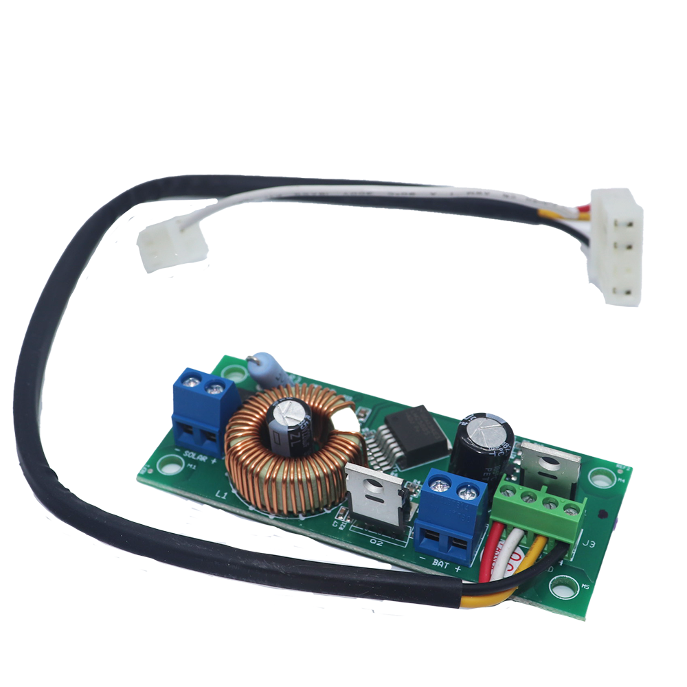
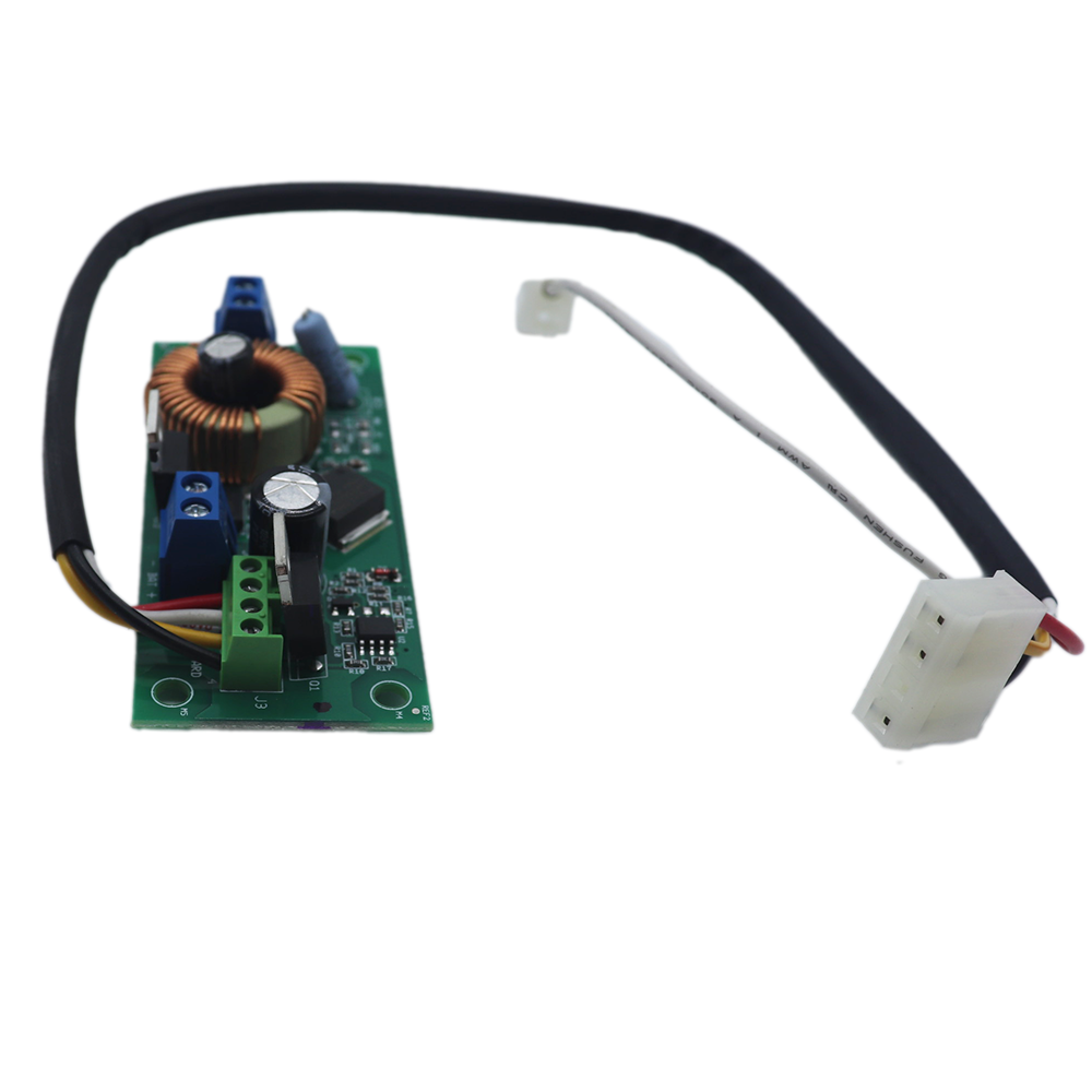
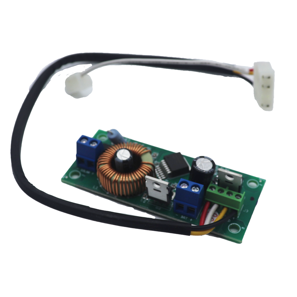
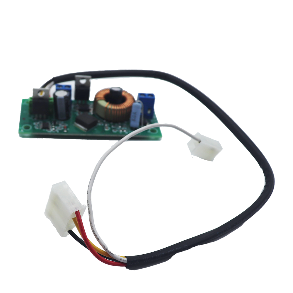
ATA SCG-01 v2.01 Solar Charger Board

Brand: ATA

ata logo

ATA SCG-01 v2.01 Solar Charger Board

Brand: ATA

ata logo

Includes:

  • 1 x SCG-01 v2.01 Solar Charger Board
  • 1 x Wiring Harness
  • 2 Years Manufacturers Warranty*
  • Free Shipping Australia-Wide*

$159.95

Availability:

Only 1 left in stock

Availability:

In stock

Includes:

  • 1 x SCG-01 v2.01 Solar Charger Board
  • 1 x Wiring Harness
  • 2 Years Manufacturers Warranty*
  • Free Shipping Australia-Wide*

Features:

  • Self Protection System for your Solar Kit
  • Genuine Product
  • Free Shipping Australia-Wide*
  • 2 Years Manufacturers Warranty*

Includes:

  • 1 x SCG-01 v2.01 Solar Charger Board
  • 1 x Wiring Harness

Compatible:

Replacing the Solar Charge Board on an ATA or B&D with identical code – SCG-01 v2.01

Weight0.2 kg
Brand

ATA

Type

N/A

Replacing your Charger Board

  • Unplug the drive unit from mains power.
  • Disengage motor using manual release cord.
  • Remove the main cover, timing cover and light diffuser, then remove the transformer, EMC board and mains power cable.
  • Fix the Charger Board  under the timing cover using four (4) M4x8 screws
  • Feed the three wire cable attached to the Charger board through the opening, then connect the three wire harness (red/yellow/black) into the control board’s “SBC-02” 5 pin connector.
  • Plug the solar shunt 5 onto the control board’s “J13” connector.

Connect the Solar Panel

  • Feed the Solar Panel’s 1 cable through black grommet on the chassis
  • Connect the red wire to the Charger Board’s 3 “SOLAR+” connector, and the black wire to the “-SOLAR” connector. WARNING! The opener will become active during the following steps.

Mount & Connect the Battery

  • Drill a 16.0mm hole in the Battery Pack enclosure (recommend at the bottom) and fit nylon gland 9 .
  • Mount the Battery Pack 2 using the mounting lugs 6 and screws 7 close to the opener.
  • Feed the 2-core 18AWG gauge cable 8 through the Battery Box’s nylon gland 9 .
  • Connect the red wire to the Battery Box’s “+” terminal, and the black wire to the “–” terminal
  • Feed the other end of the 2-core 18AWG gauge cable 8 through the drive unit’s black grommet.
  • Connect the red wire to the Charger Board’s 3 “BAT+” connector, and the black wire to the “–BAT” connector.
  • Refit the timing cover, main cover and light diffuser.

Reviews

There are no reviews yet.

Only logged in customers who have purchased this product may leave a review.

Features:

  • Self Protection System for your Solar Kit
  • Genuine Product
  • Free Shipping Australia-Wide*
  • 2 Years Manufacturers Warranty*

Includes:

  • 1 x SCG-01 v2.01 Solar Charger Board
  • 1 x Wiring Harness

Compatible:

Replacing the Solar Charge Board on an ATA or B&D with identical code – SCG-01 v2.01

Weight0.2 kg
Brand

ATA

Type

N/A

Replacing your Charger Board

  • Unplug the drive unit from mains power.
  • Disengage motor using manual release cord.
  • Remove the main cover, timing cover and light diffuser, then remove the transformer, EMC board and mains power cable.
  • Fix the Charger Board  under the timing cover using four (4) M4x8 screws
  • Feed the three wire cable attached to the Charger board through the opening, then connect the three wire harness (red/yellow/black) into the control board’s “SBC-02” 5 pin connector.
  • Plug the solar shunt 5 onto the control board’s “J13” connector.

Connect the Solar Panel

  • Feed the Solar Panel’s 1 cable through black grommet on the chassis
  • Connect the red wire to the Charger Board’s 3 “SOLAR+” connector, and the black wire to the “-SOLAR” connector. WARNING! The opener will become active during the following steps.

Mount & Connect the Battery

  • Drill a 16.0mm hole in the Battery Pack enclosure (recommend at the bottom) and fit nylon gland 9 .
  • Mount the Battery Pack 2 using the mounting lugs 6 and screws 7 close to the opener.
  • Feed the 2-core 18AWG gauge cable 8 through the Battery Box’s nylon gland 9 .
  • Connect the red wire to the Battery Box’s “+” terminal, and the black wire to the “–” terminal
  • Feed the other end of the 2-core 18AWG gauge cable 8 through the drive unit’s black grommet.
  • Connect the red wire to the Charger Board’s 3 “BAT+” connector, and the black wire to the “–BAT” connector.
  • Refit the timing cover, main cover and light diffuser.

Reviews

There are no reviews yet.

Only logged in customers who have purchased this product may leave a review.